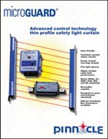
MicroGuard® by Pinnacle


The MicroGuard® safety light curtain utilizes the diverse redundancy design concept. This gives the safety light system a higher level of redundancy and control reliability. The two microprocessors are of different design, and the microprocessor or parallel programs are run and made up from different instruction sets written by different programmers.
The MicroGuard® safety light curtain self-checks every 20 milliseconds. Self-checking is the ability to electronically verify that all of the systems' critical internal circuit components and their redundant counterparts or back-ups are operating properly.
°C
Extra Safe Design
Provides tow methods of cross monitoring design. One utilizes two microprocessors and two captive contact relays and the other uses four watchdog timers monitoring the system and the captive contact relays.
External Diagnostic Message Display
Standard on all MicroGuard® safety light curtains is the "External Diagnostic Message Display"
Extensive Testing
The MicroGuard® safety light curtain incorporates extensive testing and burn-in to establish a high degree of product reliability and safety.
Redundant Captive Contact Safety Relays
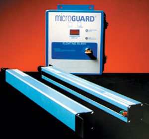
Redundant relays assure safety if an output relay should fail. The MicroGuard® utilizes safety relays which have force-guided contacts. This is a configuration where the contacts are mechanically locked together so that if one set of contacts weld, the other contacts cannot change state. If one should fail, code "Relay Fault" will be displayed on the diagnostic message display. The complete guarding system consists of two miniature pylons with a controller for system diagnostics and wiring interface.
Alphanumeric Plain English Messages
Scrolling message display shows status and fault codes of the unit. This is an excellent safety and maintenance feature which is unparalleled in the machine guarding industry for enhancing machine utilization.
Control Reliable System
Critical components of the MicroGuard® are duplicated so that a single component failure will not cause an unsafe condition. If a component does fail, the units' self-checking circuitry recognizes the situation and initiates a safe stop of the machine. The fault is then displayed on the message display.
Powerful Infrared Light Source
The MicroGuard® safety light curtain utilizes powerful, safe, and predictable infrared light as its sensing source. This gives the system greater reliability and enhances machine utilization by minimizing nuisance trips and shutdowns caused by dirt, coolants, lubrication mists and machine oils. The MicroGuard® is highly immune to EMI, RFI, and ambient light conditions and are unaffected by strobe lights and weld flash generated light sources.
Standard System Features for Metal Box and DIN-rail Controllers
Pylons:
- Heavy duty aluminum extrusions NEMA IV (IP 65)
- Replaceable infrared lens cover (acrylic)
- Sealed bulkhead positive locking circular connectors
- Mounting brackets supplied standard
- Emitter Pylon - red/green/yellow status indicators
- Optional Polycarbonate tube which will encase the pylons for high impact protection. (Pictured at right)
Cables:
- Shielded PVC 22 AWG cables with quick disconnects and strain relief fittings
- Emitter cable - 20' (6.1m) supplied standard for the Metal Box Controller Module and 22' (6.7m) supplied standard for the DIN-rail Controller Module
- Receiver cable - 8' (2.44m) supplied standard for the Metal box Controller Module and 22' (6.7m) supplied standard for the DIN-rail Controller Module
- External Alphanumeric Diagnostic & Status Message Display
- Infrared Light Source: Solid state light emitting diodes
- Beam Spacing: 1/2" (13mm) or 1" (25mm)
- Minimum Object Sensitivity
1/2" (12.7mm) beam spacing is .55" (14mm)
1" (25.4mm) beam spacing is 1.18" (30mm) - Response Time: <30 milliseconds (all sizes)
- Scanning Frequency: 5.9 Khz
- Temperature Range: 32° to 120° F (0° to -51° C)
- Shock tested to withstand high vibration applications per UL991
- Self-Checking every 20 milliseconds
- Scanning Distance: All units are supplied standard with a 20' (6.1m) scanning capability. Extended range units are available, consult your representative or the factory. Scanning distances must be specified 50' (15.24m) maximum.
- Complete Guarding System Supplied: Transmitter and receiver pylons, controller, mounting brackets, connectors and cables, installation and operation manual.
- CSA Approved, UL Listed, and CE Certified
- Two-Year Warranty
- Patented #5, 243, 183
- Category 4 Safety Device per EN954
- DeviceNet™ Fieldbus Network Compatible (optional)


